Teensy 3 & ST7565 Display
The Teensy 3 is a very compact microcontroller development system housing an ARM Cortex-M4 CPU running at up to 96MHz. A USB interface is used for both programming and communications with a PC. The design of the Teensy 3 allows it to be mounted directly onto a breadboard.
A teensyduino software package is available which enables the Teensy 3 board to be programmed using the standard Arduino IDE. Once a driver is installed on the PC the board appears as a simple COM port.
The ST7565 is an inexpensive graphical display with good image quality. Using a serial interface it requires only 5 or 6 of the Teensy digital lines. An ST7565 library is supplied in the teensyarduino package and allows the drawing of text, lines, circles, rectangles and other graphical elements.
The Teensy 3 and the ST7565 modules can be purchased for around £20 each.
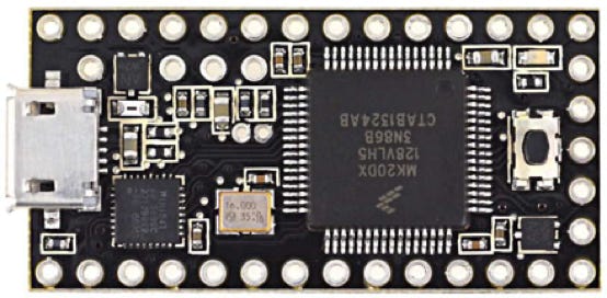
Teensy3
MK20DX128 ARM Cortex-M4 CPU
48/96 MHz
34 digital input/output pins
12 analog inputs
USB, very compact size
easily mounted on a breadboard
1.4" x 0.7" (35mm x 18m)
ST7565
Monochrome LCD
Graphical (128x64 pixels)
LED RGB backlight
Serial Interface
3.3V Supply
Note that the Teensy 4 is now available, a much faster (600MHz+) version of the Teensy 3.
Example
Shown below is a Teensy 3 and ST7565 module placed onto a breadboard. Both modules are being powered from the USB interface, including the displays backilight. Wires have been soldered onto the display module. The green backlight LED has been connected, red and blue backlight LEDs are also built in.
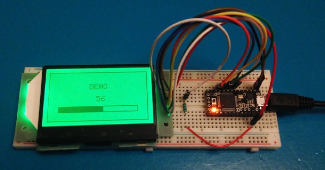
Wiring is as follows:
Teensy 3 digital 5 to '/CS' on the ST7565
Teensy 3 digital 6 to '/RST' on the ST7565
Teensy 3 digital 7 to 'A0' on the ST7565
Teesny 3 digital 8 to 'SCLK' on the ST7565
Teensy 3 digital 9 to 'SD' on the ST7565
Teensy 3 GND to GND and 'G-' on the ST7565
Teensy 3 3V3 to VDD on the ST7565
Teensy 3 3V3 to 'A+' on the ST7565 via a 100R resistor
The following Arduino code (sketch) has been programmed into the Teensy 3:
#include "ST7565.h" // Library file for display
int ledPin=13;
int commandByte;
char charBuffer[15];
elapsedMillis ledTimer;
ST7565 glcd(9, 8, 7, 6, 5); // define IO lines used for display
void setup() {
Serial.begin(9600); // Enable USB serial interface
pinMode(ledPin, OUTPUT);
glcd.begin(0x15); // set contrast
glcd.clear();
glcd.drawrect(0, 0, 128, 64, BLACK);
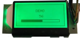
glcd.drawstring(64-4*3, 2, "DEMO");
glcd.display();
glcd.drawrect(13, 45, 102, 8, BLACK);
glcd.display();
}
void loop() {
if (ledTimer>1980) { digitalWrite(ledPin, HIGH); }
if (ledTimer>2000) { digitalWrite(ledPin, LOW); ledTimer = 0; }
if (Serial.available() > 0) {
commandByte = Serial.read();
digitalWrite(ledPin, HIGH);
if (commandByte==65) Serial.write("TEENSY3");
if (commandByte==66) drawBarGraph();
ledTimer=1500;
}
}
void drawBarGraph() {
int readBytes=Serial.readBytes(charBuffer,1); // Read one character
if (readBytes<1) return;
int value=charBuffer[0];
if (value>100) value=100;
dtostrf(value, 4, 0, charBuffer); // Convert integer to decimal string
glcd.drawstring(64-5*3, 4, charBuffer);
glcd.fillrect(14, 46, 100, 6, WHITE);
glcd.fillrect(14, 46, value, 6, BLACK);
glcd.display();
Serial.write(commandByte);
}
The above code has the following functionality:
The setup routine, called once on power up, enables the USB communications, sets IO pin 13 as an output (an LED is connected to this pin on the Teensy 3), draws a box around the edge of the display, prints the word DEMO on the display, and then draws an empty bar graph.
The loop routine, which continues forever, checks the USB port for a comand byte.
When the command byte 'A' is received (decimal 65) the module transmits "TEENSY3" back to the PC.
When the command byte 'B' is received (decimal 66) the 'drawBarGraph' function is called. This function receives one more byte, and then updates the bar graph to show the value of the byte and displays the byte as a decimal number. A 'B' character is sent back to the PC to indicate that the command has been completed.
The ledTimer variable is automatically incremented every 1ms. This variable is used to control the flashing of the LED on the Teensy 3, on for 20ms every 2 seconds. If a command is received then the LED is kept on for at least 500ms to indicate the module is busy.
The ST7565 library keeps a buffer for the display in RAM. All drawing takes place in the buffer, which is copied to the display using the 'glcd.display()' function. There are a number of faults in the ST7565 library which are easily fixed, contact us for more information.
Copyright 2022 APG Consultancy LTD
Email: info@apg-consultancy.co.uk